In the industry, flank locking locknuts stand as a testament to precision engineering and unwavering grip. These specialized nuts, often entrusted with critical applications in aerospace, heavy machinery, and beyond, offer unparalleled resistance to vibration and loosening, ensuring safety and performance even under the most demanding conditions.

Construction:

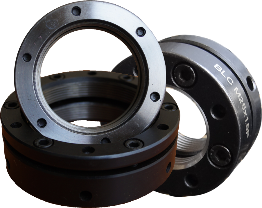
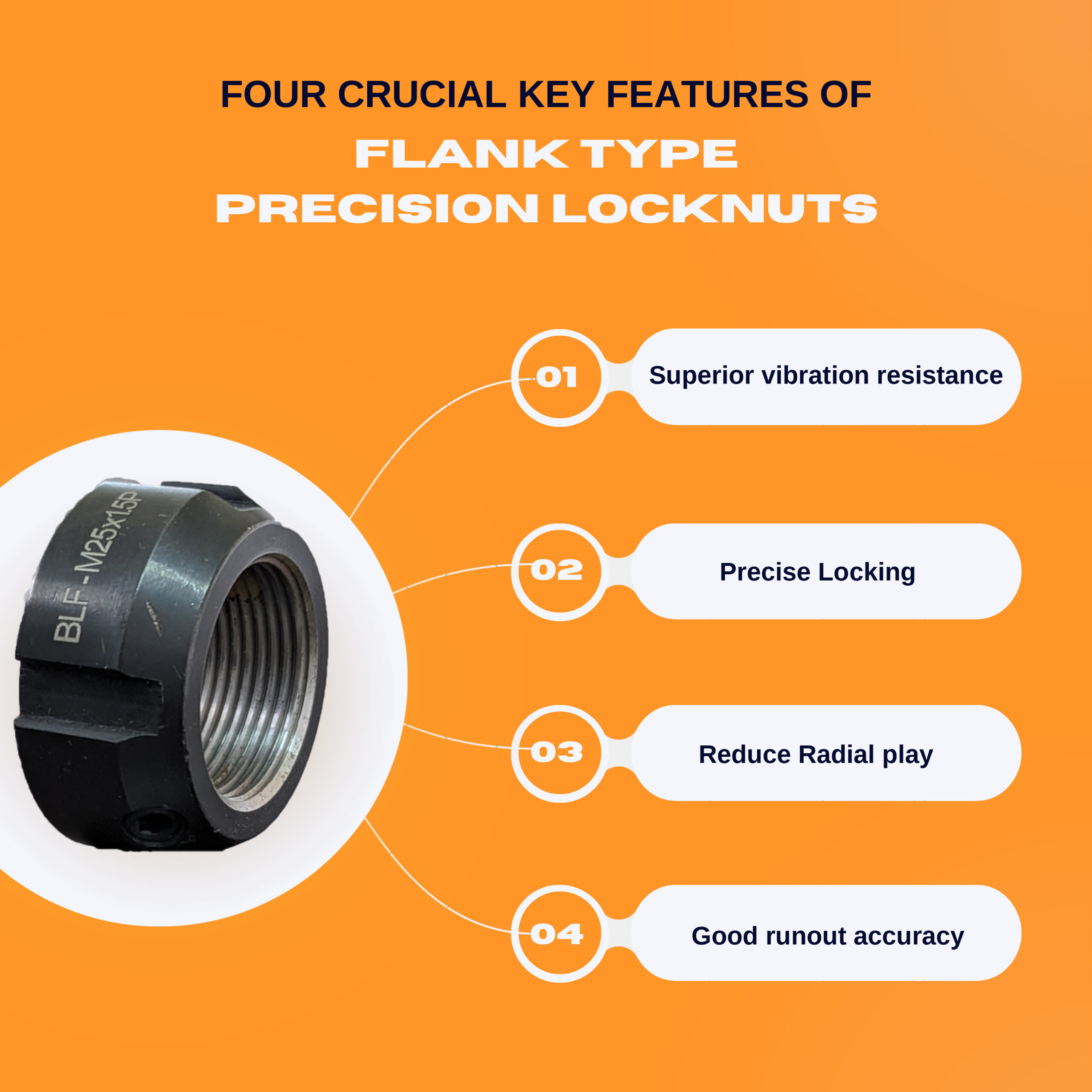
Flank locking-type locknuts are designed with a distinct construction that sets them apart from traditional locknuts. The key feature includes flanks or serrations on the nut’s internal or external surface. These serrations engage with the threads of the bolt or stud, creating a positive locking mechanism. The design of locking can make the threads of fixed copper completely mesh with the counter-threads and lead to a perfect effect of let-off. A 30° lock nut design reduces the torque resulting from tightening a screw. The interaction between the flanks and the threads prevents self-loosening, ensuring a more secure and stable connection.

Benefits:

Enhanced Security: The flank locking mechanism reduces the risk of loosening due to vibration or dynamic loads, providing a more secure fastening solution.

Resistance to Environmental Factors: Flank locking-type locknuts are often constructed with materials that offer resistance to corrosion and other environmental factors, ensuring long-term reliability in various conditions.

Ease of Installation: The design of flank locking type locknuts allows for straightforward installation without the need for specialized tools. This simplicity contributes to time and labor efficiency in assembly processes.

Reusable: Unlike some traditional locking methods that may involve deformation or damage during installation, flank locking-type locknuts are generally reusable without compromising their locking capabilities.

Choosing the Right Locknut:

Selecting the ideal flank locking locknut requires careful consideration of several factors:


Thread Size and Pitch: Ensure the nut’s thread size and pitch match those of the bolt or stud it will be paired with.


Material Matters: Choose a material suited for the environment the nut will face. High-strength steel is the standard, but stainless steel and brass offer additional properties for specific needs.


Locking Insert Options: Different types of locking inserts exist, each with its own advantages and limitations. Consult with a professional to determine the best option for your application.


Load and Vibration Requirements: Consider the specific load and vibration conditions of the application. Different flank locking type locknuts may be designed to handle varying levels of stress and movement.

Applications:

Flank locking type locknuts find application in a wide range of industries and scenarios, including:

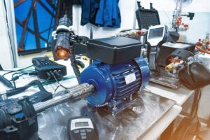
Automotive: In critical automotive components where vibration resistance is paramount, such as in suspension systems and engine assemblies.

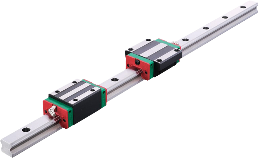
Industrial Machinery: For securing components in heavy machinery subject to constant vibrations and dynamic loads.

Aerospace: In aircraft and spacecraft, where the reliability of fasteners is crucial for safety and performance.

Construction: Used in construction applications where stability and resistance to environmental factors are essential.

Medical Equipment: Where precision and patient safety are paramount, flank locking locknuts play a crucial role in ensuring the integrity of critical medical devices.

Conclusion:

The flank-locking type locknut has become a valuable asset in the toolkit of engineers and manufacturers, offering a robust solution to the challenge of self-loosening fasteners. With their innovative design, ease of installation, and resistance to environmental factors, these locknuts provide a reliable means of securing critical components in various industries. As technology continues to advance, flank locking-type locknuts are likely to play an increasingly important role in ensuring the safety and reliability of mechanical systems.

Flank locking locknuts are more than just fasteners; they are symbols of unwavering reliability and unwavering performance. Their ingenious design, coupled with their adaptability and reusability, makes them the undeniable choice for applications where failure is not an option. So, the next time your project demands a grip that refuses to budge, turn to the flank locking locknut – a testament to engineering excellence and a silent guardian of safety and precision.

Remember:

Always consult with a qualified engineer to ensure you’re using the correct fasteners for your specific application, If in doubt feel free to contact us.

Never overtighten flank locking locknuts, as this can damage them and reduce their effectiveness.

Regularly inspect flank locking locknuts for any signs of wear or damage, and replace them if necessary.

By following these tips and choosing the right flank locking locknuts, you can ensure the smooth operation and safety of your critical equipment, even in the face of the most demanding challenges.

Introduction:

In the dynamic world of manufacturing, Computer Numerical Control (CNC) machines have revolutionized how we create intricate and precise components. At the center of these machines lies a crucial component that often goes unnoticed – the ball screw. This ballscrew plays a pivotal role in translating rotational motion into precise linear movement, making it an indispensable element in CNC machining.

Understanding Ball Screws:

A ball screw is a mechanical linear actuator that converts rotational motion into linear motion with minimal friction. Its design consists of a screw shaft with helical grooves, known as threads, and a ball nut containing recirculating ball bearings. The interaction between the screw and the nut enables smooth and efficient motion, ensuring precision in the CNC machining process.

Key Features of Ball Screws:

Precision and Accuracy:

Ball screws excel in providing high levels of precision and accuracy in CNC machines. The recirculating ball bearings reduce friction, resulting in smoother movement and eliminating backlash – the undesirable play or movement in the system.

High Efficiency:

The rolling motion of the ball bearings along the helical grooves of the screw reduces frictional losses, making ball screws highly efficient in converting rotational energy into linear motion. This efficiency contributes to the overall performance and speed of CNC machines.

Reduced Wear and Tear:

The design of ball screws minimizes contact between moving parts, reducing wear and tear. This feature enhances the longevity of the CNC machine, making it a cost-effective and reliable choice for manufacturing processes.

Backlash Elimination:

Backlash is a common issue in machinery, causing a delay in response and decreased accuracy. Ball screws address this problem by providing a tight fit between the screw and nut, ensuring that there is minimal play in the system.

Location of Ball Screws in CNC Machines:

Ball screws are typically located in the axes of CNC machines, where precise linear motion is required. The primary areas include:

X-Axis:

The ball screw is commonly found on the X-axis, which represents the horizontal movement of the CNC machine’s cutting tool or workpiece. This ensures accurate and controlled lateral motion during machining processes.

Y-Axis:

In CNC machines with multiple axes, the Y-axis often incorporates a ball screw to enable precise vertical movement. This is crucial for creating intricate details and complex geometries.

Z-Axis:

The Z-axis, responsible for the depth or height of the cutting tool, also features a ball screw. This ensures controlled and accurate movement along the vertical axis, contributing to the overall precision of the machining process.

Applications of Ball Screws in CNC Machines:

Milling and Machining Centers:

CNC milling machines and machining centers rely heavily on ball screws to precisely move the cutting tool along the desired path. This is crucial for creating intricate designs and achieving high-quality surface finishes.

Lathe Machines:

In CNC lathe machines, ball screws facilitate the accurate movement of the cutting tool, allowing for the production of symmetrical and precisely dimensioned components.

3D Printing:

The additive manufacturing process in 3D printing involves precise layer-by-layer deposition of material. Ball screws play a vital role in controlling the movement of the print head, ensuring accurate and repeatable results.

Conclusion:

In the realm of CNC machining, the significance of ball screws cannot be overstated. These precision components, strategically located in the axes of the machine, are the driving force behind the accurate and efficient movement of tools and parts. As technology continues to advance, the role of ball screws in manufacturing processes is likely to evolve, paving the way for even greater precision and innovation in the world of CNC machining.

Introduction

In the realm of mechanical engineering, couplings play a crucial role in transmitting torque and motion between shafts. Among the various types of couplings available, bellows couplings stand out for their exceptional ability to accommodate misalignments and damp vibrations. This blog delves into the world of bellow couplings, exploring their intricacies, advantages, and applications.

Construction of a Bellows Coupling

At the heart of a bellows coupling lies a flexible metallic bellows, typically composed of stainless steel. This bellows, resembling a series of interlocked convolutions, acts as the coupling’s primary element, enabling it to compensate for misalignments and absorb vibrations. The bellows is securely fastened to hubs or flanges on either end, connecting the driving and driven shafts.

Advantages of Bellows Couplings

Bellows couplings offer a multitude of advantages over other coupling types, making them a preferred choice in various applications. Their key strengths include:

 Exceptional Misalignment Accommodation:

Bellows couplings can effectively handle both parallel and angular misalignments, ensuring smooth power transmission even when shafts are not perfectly aligned.

 Zero Backlash:

Unlike some couplings that exhibit backlash, bellows couplings transmit torque without any play or undesirable movement, ensuring precise positioning and control.

 Torsional Stiffness:

Bellows couplings maintain their torsional rigidity, allowing for accurate torque transmission without compromising on shaft alignment.

 Vibration Damping:

The inherent flexibility of the bellows effectively dampens vibrations, minimizing noise and protecting machinery from vibration-induced damage.

Maintenance-Free Operation:

Bellows couplings are typically self-lubricating and require minimal maintenance, reducing downtime and associated costs.

Things to Consider While Purchasing

When selecting a bellows coupling for a specific application, several factors need to be considered:

 Torque Capacity:

The coupling’s torque capacity must exceed the maximum torque required by the application.

 Speed Rating:

Ensure the coupling’s speed rating is compatible with the operating speed of the shafts.

 Misalignment Tolerance:

Choose a coupling with misalignment tolerance that adequately accommodates the expected misalignment in the system.

 Material Compatibility:

The coupling’s material should be compatible with the operating environment and the fluids or chemicals it may encounter.

Mounting Options:

Select a coupling with mounting options that suit the specific installation requirements.

Applications of Bellows Couplings

The versatility of bellows couplings makes them suitable for a wide range of applications, including:

 Servo Systems:

Bellows couplings are widely used in servo systems due to their high precision and zero backlash characteristics.

 Pump Drives:

In pump applications, bellows couplings effectively handle misalignments and vibrations, ensuring consistent flow and reducing wear and tear.

 Robotics:

Bellows couplings are well-suited for robotic applications due to their ability to accommodate complex motions and absorb vibrations.

 Machine Tools:

In machine tools, bellows couplings provide precise torque transmission and vibration damping, ensuring accurate machining operations.

 Medical Devices:

Bellows couplings are used in medical devices to transmit torque and motion with utmost precision and reliability.

Conclusion

Bellows couplings have firmly established themselves as indispensable components in various mechanical systems. Their ability to accommodate misalignments, damp vibrations, and transmit torque with precision makes them ideal for applications demanding high performance and reliability. As technology advances, bellows couplings continue to evolve, offering enhanced capabilities and expanding their reach into new domains.


What is a ball screw whip and why does it happen?


Ball screws are critical components in various mechanical systems, serving as efficient devices for converting rotary motion into linear motion. However, an inherent limitation of ball screw technology is its inverse relationship between speed and length. As the ball screw shaft extends, it becomes increasingly prone to whipping, akin to a jump rope in motion. This whipping behavior imposes constraints on achieving maximum travel distances, especially when high speeds are essential.

Understanding the Causes of Ball Screw Whip:

Critical Speed Exceedance:

The critical speed of a ball screw assembly plays a pivotal role in determining its permissible operating speed, alongside the characteristic speed. Characteristic speed is influenced by factors related to the ball nut, encompassing the ball return system and ball mass. Advances in ball nut manufacturing and ball recirculation methods have elevated characteristic speeds for most ball screw assemblies. Nevertheless, critical speed remains a limiting factor.

Critical speed, in the context of a rotating shaft like a ball screw assembly, refers to the angular velocity that induces the natural frequency or first resonant frequency of the assembly. Operating the shaft at its natural frequency can trigger resonance, potentially causing severe damage or destruction of the assembly.

 Insufficient Stiffness:

Insufficient stiffness in either the ball screws itself or its supporting structures can significantly diminish critical speeds, rendering the system more susceptible to whip. The term “critical speed” refers to the angular velocity at which the natural frequency of a rotating assembly is excited. When the stiffness of the ball screw or its support structures is inadequate, it compromises the system’s ability to resist deflection and whipping during rotation.

In practical terms, lower stiffness in the ball screw allows greater deflection, especially as the length of the screw increases. This increased deflection, coupled with reduced stiffness in the supporting structures, exacerbates the tendency for the ball screw to whip in motion. As the system operates at lower critical speeds, it becomes more prone to resonance, amplifying the risk of detrimental effects such as increased vibrations, heightened noise levels, and potential damage to the ball screw assembly.

Addressing and improving the stiffness of both the ball screw and its supporting structures are essential measures to mitigate the risk of lower critical speeds and the associated challenges of whip. Enhancing stiffness helps to maintain the integrity of the rotating assembly, enabling it to resist excessive deflection and operate within a more favorable range of critical speeds.

In the vast and often underappreciated world of fasteners, the radial type locknut stands out as a silent guardian of secure mechanical assemblies. While its unassuming cylindrical form may lack the visual appeal of its hexagon-headed brethren, its unique design and remarkable functionality make it an indispensable component in countless applications.

Construction:

Unlike traditional nuts, the radial type locknut features a strategically placed split section along its body. This seemingly minor detail unlocks its superpower: the ability to contract radially, meaning it squeezes threads inwards as it’s tightened. This seemingly simple action generates a powerful grip on the mating threads, creating a secure and vibration-resistant connection.

Key Advantages of the Radial Design:

This radial squeeze translates into several distinct advantages:

  • Superior Vibration Resistance: The inward bite of the nut effectively counteracts the loosening forces of vibration, ensuring your assembly remains rock-solid even in the most demanding environments, be it a high-speed machine or a rumbling vehicle.
  • Precision Locking: The controlled radial contraction delivers consistent locking torque, eliminating the guesswork and potential over-tightening associated with traditional nuts. This ensures optimal preload and prevents thread damage.
  • Reduced Radial Play: By hugging the threads, the nut minimizes side-to-side movement, a crucial factor in applications where precise shaft alignment is paramount, such as in robotics or optical instruments.


Applications:

The radial type locknut’s talents extend far beyond a singular role. You’ll find them securing vital components in a wide range of industries:

  • Ball Screws: These unsung heroes of linear motion rely on radial locknuts to keep their threads from unraveling under immense forces, ensuring smooth and accurate motion.
  • Bearings: From the humble bicycle wheel to the mighty industrial turbine, bearings keep the world spinning, and radial locknuts are the silent guardians against bearing slippage, preventing catastrophic equipment failure.
  • Precision Shafts: Whether it’s a delicate surgical instrument or a high-speed robotic arm, precise shaft alignment is vital for accuracy and safety. The radial locknut’s unwavering grip ensures these shafts stay true, one vibration-proof turn at a time.

Limitations to Consider:

While undeniably effective, radial locknuts also have certain limitations:

  • Axial Force Sensitivity: Unlike traditional nuts, radial locknuts are not designed to withstand significant axial (pulling) forces. Excessive pulling can cause the nut to disengage, potentially compromising the assembly’s integrity.
  • Application Specificity: The radial design may not be suitable for all applications. Assemblies requiring frequent adjustments or disassembly might benefit from a different locking mechanism.
  • Material Restrictions: While typically made from steel for durability, radial locknuts are not as readily available in exotic materials like titanium or stainless steel, which might be required for specific environments.


Things to Consider while Purchasing Radial Locknuts:

Despite these limitations, radial locknuts remain a valuable tool in the mechanical engineer’s arsenal. When selecting the right one, remember these key considerations:

  • One-sided grind: Choose Locknut that have smooth-grinded surface on one side. A traditional locknut relies solely on its radial squeeze to grip the mating threads. However, this grip can be compromised by slight imperfections or inconsistencies on the mating surfaces. This is where the one-sided grind comes in. By strategically grinding one side of the nut, we essentially create a micro-wedge. This wedge, when tightened, amplifies the radial force, digging deeper into the mating threads and establishing a significantly tighter grip.
  • Material: Steel reigns supreme for its durability, but nylon options offer weight savings and corrosion resistance, making them ideal for specific environments.
  • Thread Size and Pitch: Just like a regular nut, ensure the locknut’s thread size and pitch match the application perfectly.
  • Locking Feature: Some radial locknuts come equipped with an additional grub screw for enhanced bite, while others rely solely on their inherent radial force. Choose the one that best suits your assembly’s needs.
  • Consult Professional: Remember, consulting with the right professional can be the difference between a low quality and high quality locknut. If you have any doughts feel free to contact us. We are always happy to guide you.

In Conclusion:

The radial type locknut may not boast fancy aesthetics or a glamorous name, but its silent grip and unwavering dedication to secure assemblies make it a true hero in the world of mechanical engineering. So, the next time you tighten a nut, remember the unsung heroes – the radial type locknuts – who keep our world securely fastened, with the limitations duly considered, one vibration-proof turn at a time.


Spider couplings are a type of flexible coupling that uses a flexible spider element to connect two shafts. They are known for their high torsional flexibility, misalignment accommodation, and vibration-dampening capabilities. Spider couplings are widely used in a variety of industrial applications, including power transmission, motion control, and robotics.

What is a Spider Coupling?

A spider coupling consists of two hubs, a spider element, and a set of clamping bolts. The hubs are attached to the two shafts that need to be connected, and the spider element is sandwiched between the hubs and clamped in place. The spider element is typically made of a flexible material, such as elastomer or polyurethane. The type of flexible material used depends on the specific application requirements. Some of the most common materials used include:

  • Nitrile Butadiene Rubber (NBR): The most common and economical material for spider couplings. It offers good resilience, elasticity, and resistance to oil, hydraulic fluid, and most chemicals. The operating temperature range is from -40°F to +212°F (-40°C to +100°C).
  • Polyurethane (PU): Provides higher torque capacity than NBR and is resistant to oil, chemicals, and abrasion. It has a good damping effect and operates in a temperature range of -30°F to 160°F (-30°C to 71°C).
  • Hytrel: A thermoplastic elastomer that offers high strength, stiffness, and wear resistance. It is resistant to high temperatures, chemicals, and solvents. The operating temperature range is from -40°F to 250°F (-40°C to 121°C).
  • Nylon: A lightweight and strong material that offers good resistance to abrasion and chemicals. It is not as flexible as elastomers but can be used in some applications where high torsional stiffness is required.
  • Neoprene: A synthetic rubber that is resistant to heat, oil, and chemicals. It is not as flexible as NBR or PU but is suitable for some high-temperature applications.

The specific choice of material will depend on the specific application requirements, such as the torque capacity, misalignment tolerance, operating temperature, and environmental conditions.


How Does a Spider Coupling Work?

Imagine you’re trying to connect two spinning shafts together, like a bike’s pedals to its wheels. But the shafts aren’t perfectly lined up, and they might wobble a bit as they spin. That’s where a spider coupling comes in.

Think of a spider coupling as a flexible bridge between the two shafts. It’s made of a stretchy material, like rubber, with a bunch of interlocking fingers that grab onto the shafts. When the shafts spin, the spider coupling stretches and flexes to keep them connected, even if they’re not perfectly aligned.

Spider couplings are pretty neat because they can handle a little bit of misalignment, dampening vibrations and making for a smoother ride. They’re also pretty tough and can handle a lot of torque, making them perfect for pumps, fans, and conveyor belts.

When the two shafts rotate, the spider element twists and flexes to accommodate any misalignment or vibration. This allows the shafts to transmit power smoothly and efficiently, even in harsh operating conditions.

So, if you ever see a machine with two spinning shafts that don’t quite line up, there’s probably a spider coupling doing its thing behind the scenes, keeping everything running smoothly.


Benefits of Spider Couplings

Spider couplings offer several benefits, including:

  • High torsional flexibility: Spider couplings can accommodate a high degree of torsional misalignment, making them ideal for applications where the shafts are not perfectly aligned.
  • Misalignment accommodation: Spider couplings can also accommodate misalignment in other planes, such as axial and radial misalignment. This makes them ideal for applications where the shafts are subject to movement and vibration.
  • Vibration dampening: Spider couplings can dampen vibration, which can help to protect other components in the system from damage.
  • Long service life: Spider couplings are typically made of durable materials and have a long service life.

Things to Consider When Purchasing a Spider Coupling

When purchasing a spider coupling, there are some factors to consider, including:

  • Torque capacity: Choose a coupling with a torque capacity that exceeds the maximum torque that will be transmitted through the system.
  • Bore size: Choose a coupling with a bore size that matches the diameter of the shafts that need to be connected.
  • Misalignment capacity: Choose a coupling with a misalignment capacity that exceeds the maximum misalignment that will occur in the system.
  • Operating environment: Consider the operating environment when selecting the materials and construction of the coupling. For example, if the coupling will be used in a corrosive environment, choose a coupling made of corrosion-resistant materials.
  • Speed: Consider the operating speed of the shafts. Some spider couplings have limitations on maximum speed, so ensure the selected coupling can handle the required rotational speed.
  • Cost: Evaluate the cost of the coupling in relation to its performance and durability. Balance the initial cost with the long-term benefits of a reliable coupling.
  • Specific Application Requirements: Consult with experts or refer to specific application guidelines to determine any unique requirements for your application. Consider factors such as shock loads, high-cycle fatigue, or food-grade compatibility.

Applications for Spider Couplings

Spider couplings are used in a variety of industrial applications, including:

  • Power transmission: Spider couplings are widely used in power transmission applications, such as connecting motors to pumps, compressors, and other equipment.
  • Motion control: Spider couplings are also used in motion control applications, such as connecting servo motors to actuators and robots.
  • Robotics: Spider couplings are commonly used in robotic applications, where they provide flexibility and misalignment accommodation.
  • Oil and Gas: In the oil and gas industry, spider couplings are used to connect pumps, compressors, and other equipment. They are well-suited for these applications due to their resistance to oil, chemicals, and harsh operating conditions.
  • Mining: Spider couplings play a vital role in mining operations, connecting conveyors, crushers, and other machinery. Their ability to withstand high torque and vibration makes them suitable for the demanding conditions of mining environments.
  • Manufacturing: Spider couplings are widely used in manufacturing plants to connect motors, drives, and other equipment. Their flexibility and reliability contribute to the efficient operation of manufacturing processes.

Conclusion

Spider couplings are a versatile and reliable solution for power transmission and motion control applications. They offer several benefits, including high torsional flexibility, misalignment accommodation, vibration dampening, and long service life. When purchasing a spider coupling, it is important to consider the torque capacity, bore size, misalignment capacity, and operating environment.


What is a Slit Coupling?

Beam couplings are a type of coupling that is used to connect two shafts together in order to transmit power and motion between them. The coupling consists of two hubs, one on each shaft, and a flexible beam that connects them. The beam can be made of various materials such as stainless steel, aluminum, or titanium, and it is designed to flex and absorb misalignments between the shafts. Beam Coupling compensates for the following types of misalignment: Axial and angular misalignment.

Benefits of Slit Couplings

One of the main advantages of beam couplings is their ability to handle misalignment between the two shafts. Misalignment can occur due to various reasons such as thermal expansion, vibration, or manufacturing tolerances. A beam coupling can compensate for this misalignment by flexing and allowing the two shafts to remain connected even if they are not perfectly aligned.

Another advantage of beam couplings is their compact size. Because the coupling relies on a flexible beam rather than a bulky mechanical mechanism, it can be used in applications where space is limited. In addition, beam couplings are lightweight and easy to install, making them a popular choice in a variety of industries.

How does a Beam Coupling work?

The beam coupling is installed on the two shafts, and the bolts are tightened to secure it. When the motor turns the first shaft, the torque is transmitted to the beam coupling. The beams in the coupling flex to accommodate any misalignment between the two shafts. The torque is then transmitted to the second shaft, which turns the load.

Applications of Beam Couplings

Beam couplings are also known for their high torsional stiffness, which means that they can transmit high torque loads without significant torsional deflection. This is important in applications where precise motion control is required, such as in robotics or machine tools.

There are different types of beam couplings available in the market, such as single-beam couplings, double-beam couplings, and helical beam couplings. Each type has its own advantages and disadvantages depending on the specific application requirements.

Key considerations when selecting an aluminum flexible coupling:

  • Torque capacity: Ensure the coupling can handle the maximum torque of the application.
  • Misalignment accommodation: Choose a coupling that can accommodate the expected misalignment.
  • Speed rating: Select a coupling rated for the application’s operating speed.
  • Bore size: Match the coupling’s bore size to the shaft sizes it will connect.
  • Operating environment: Ensure the coupling’s material and finish suit the operating conditions.
  • Cost: Balance budget considerations with the application’s requirements.
  • Material of construction: Aluminum or stainless steel should be compatible with the operating environment and loads.

Contact Balaji Engineering Works or Consult a qualified engineer for assistance in selecting the appropriate coupling for your specific application.

Conclusion
In conclusion, beam couplings are a versatile and reliable way to connect two shafts. Their ability to compensate for misalignment, compact size, high torsional stiffness, and ease of installation make them a popular choice in a variety of industries. If you are looking for a coupling that can handle misalignment and transmit high torque loads, a beam coupling may be the right choice for your application.


What is a Slit Coupling?

A slit-type coupling is a mechanical device used to connect two shafts to transmit torque and rotation from one to the other. It is a type of flexible coupling that can accommodate small amounts of misalignment between the shafts while still maintaining an efficient transmission of power. Slit Coupling compensates for the following types of misalignment: Angular misalignment.

How does a Slit Coupling work?

The slit-type coupling consists of two halves, each with a series of radial slits cut into them. The slits are arranged in such a way that they interlock with the corresponding slits on the other half when the two halves are brought together. This interlocking design allows for a flexible connection between the two shafts, while still maintaining a secure grip on both shafts.

Benefits of Slit Couplings

One of the key benefits of slit-type coupling is its ability to compensate for misalignment between the two shafts. Because the slits can flex slightly, the coupling can accommodate small amounts of angular and radial misalignment without placing undue stress on either shaft. This makes it a useful choice for applications where the shafts may be subject to vibration or where alignment may be difficult to achieve.

Another advantage of the slit type coupling is its simplicity. Unlike other types of couplings that may require lubrication or maintenance, slit-type coupling is relatively maintenance-free. It is also easy to install and remove, making it a popular choice for applications where frequent shaft disconnection is necessary.

In terms of specifications, slit-type flexible couplings are available in industry standard sizes, with diameters ranging from 8 to 30mm. They can control angular misalignment up to 2 degrees and parallel misalignment from 0.15 to 0.20mm (0.005 to 0.007 inches).

Limitations of Slit Couplings

However, there are some limitations to the slit type coupling. One of the most, significant is its inability to accommodate large amounts of misalignment. If the shafts are significantly out of alignment, the coupling may fail to transmit power efficiently or may even cause damage to the shafts themselves. Additionally, because the coupling relies on a tight fit between the slits in each half, it may not be suitable for applications where there is a significant difference in diameter between the two shafts.

Conclusion

In summary, slit-type coupling is a flexible and reliable mechanical device for transmitting torque and rotation between two shafts. Its ability to accommodate small amounts of misalignment and its simplicity makes it a popular choice for many applications. However, it is important to be aware of its limitations and to choose the appropriate coupling for the specific requirements of each application.


Key considerations when selecting an aluminum flexible coupling:


Torque capacity: Ensure the coupling can handle the maximum torque of the application.


Misalignment accommodation: Choose a coupling that can accommodate the expected misalignment.


Speed rating: Select a coupling rated for the application’s operating speed.


Bore size: Match the coupling’s bore size to the shaft sizes it will connect.


Operating environment: Ensure the coupling’s material and finish suit the operating conditions.


Cost: Balance budget considerations with the application’s requirements.


Material of construction: Aluminum or stainless steel should be compatible with the operating environment and loads.


Contact Balaji Engineering Works or Consult a qualified engineer for assistance in selecting the appropriate coupling for your specific application.


At Balaji Engineering Works, we specialize in manufacturing and supplying aluminum slit-type flexible couplings as part of our linear motion equipment clamping solutions. Our couplings are designed to compensate for axial, radial, and angular misalignments, and they are simple and easy to assemble. They offer high-torsional stiffness and response, and their one-piece construction ensures zero backlash and low reaction force.

Couplings are devices that connect two shafts and absorb some misalignment between them. They work by allowing a certain degree of misalignment and flexing the flexible insert to reduce stress on the shafts and the bearings. Couplings are used in a wide range of applications, from power generation and transmission to robotics and medical devices. Here are some specific examples of coupling applications:

  • Power generation and transmission: Couplings connect turbines to generators, generators to transformers, and transformers to transmission lines.
  • Oil and gas: Couplings connect pumps, compressors, and other rotating equipment in oil and gas production and processing facilities.
  • Mining: Couplings connect conveyors, crushers, and other rotating equipment in mining operations.
  • Manufacturing: Couplings connect motors, gearboxes, and other rotating equipment in a wide variety of manufacturing applications.
  • Transportation: Couplings connect engines to transmissions, transmissions to axles, and axles to wheels in cars, trucks, and other vehicles.
  • Robotics: Couplings connect motors to joints in robots.
  • Medical devices: Couplings connect motors to impellers in pumps and other medical devices.
  • Industrial machinery: Couplings connect the shafts of motors, pumps, compressors, and other industrial machinery.
  • Automotive applications: Couplings connect the shafts of engines, transmissions, and differentials in cars and trucks.
  • Aerospace applications: Couplings connect the shafts of engines, propellers, and other components in aircraft and spacecraft.
  • Marine applications: Couplings connect the shafts of engines, propellers, and other components in ships and boats.Application Machine

Here are some specific examples of coupling applications:

  • In a conveyor system, couplings connect the shafts of the different conveyor belts. This allows the belts to be run at different speeds and in different directions.
  • In a power plant, couplings connect the shafts of the turbine and generator. This allows the turbine to drive the generator, which produces electricity.
  • In a paper mill, couplings connect the shafts of the different rollers and drums that process the paper. This allows the paper to be moved through the mill and processed into finished products.
  • In a machine tool, couplings connect the shafts of the motor, spindle, and feed axes. This allows the machine tool to operate and produce accurate parts.

When it comes to machines, the importance of ensuring their efficiency and consistency of operation cannot be overstated. One of the components that can contribute to this is the locknut. Locknuts are used to secure bearings, gears, and other power transmission products to shafts and spindles with a high degree of stiffness.

However, traditional industrial lock nuts with washers are not suitable for super-precise machine bearings because they have relatively large manufacturing tolerances. This is where precision locknuts come into play.

Precision locknuts are designed to adjust, preload, and secure bearings, gears, and other power transmission products with a high degree of accuracy. They are made to correspond with standard bearing sizes and are sometimes called bearing locknuts. These locknuts are typically used in CNC lathe machines, CNC grinding machines, and other similar machines.

The process of manufacturing precision locknuts involves several steps. First, the lock nut raw material is cut down to size. Then, CNC and VMC machining operations are performed to shape the locknut to its desired form. After that, the machined workpiece is taken out for the treatment process to prevent it from corrosion. Once the treatment process is complete, Allen bolts are placed in holes and fitted to give the locknuts their desired locking capabilities.

To ensure the quality of the precision locknuts, runout testing, visual inspections, roughness testing, and hardness testing are performed. Only the lock nuts that pass all of these test criteria are packed in anti-corrosive packing boxes and made available for use.

Precision locknuts are available in various locking methods, including set screws, clamping screws, shoes, and resilient rings. The set screws are typically located on the face or periphery of the locknut, and they are used to lock the female threads of the locknut to the male threads of the shaft. By tightening the set screws, the thread clearance of the locknut is eliminated, ensuring a tight fit.

One example of precision locknuts is the BLC series, which is a Clasp-Locking nut and features an elastomer steel body, axial locking, and forced locking. This series provides a three-fold increase in locking capability over traditional locknuts, making it ideal for harsh working environments where locknuts are easily loosened.

Another example is the BLR series, which uses a radial locking arrangement through a mechanism of screw tightening. This series employs 2-way, 3-way, or 4-way radial locking and is ideally suited for applications where locknut space is limited.

Finally, the BLF series uses a locking method that involves tightening screws at a 30-degree angle to the threads. This design allows the threads of the fixed copper to mesh perfectly with the counter-threads, resulting in a perfect effect of let-off. The 30-degree locknut design also reduces the torque resulting from tightening a screw.

Choosing high-quality precision locknuts is crucial for ensuring the efficiency and consistency of machine operation. By understanding the different types of precision locknuts and their locking methods, you can make an informed decision when selecting the right lock nut for your machine.
One important aspect to consider when selecting a precision locknut is the level of precision required for the application. Depending on the application, a locknut with a higher level of precision may be necessary to ensure optimal performance and longevity of the equipment. For example, in high-speed applications or those with high loads, a locknut with a higher level of precision may be necessary to prevent excessive wear or damage to the equipment.

Another important consideration when selecting a precision locknut is the material it is made from. The material of the locknut can have a significant impact on its performance and durability. Some materials commonly used for precision locknuts include stainless steel, carbon steel, and brass.

It’s also important to consider the installation process for precision locknuts. Proper installation is critical to ensure that the locknut performs as intended and provides the necessary level of preload or locking force. In some cases, specialized tools or equipment may be required to properly install the locknut.

Finally, it’s important to source precision locknuts from a reputable supplier that can provide high-quality products and reliable service. Working with a trusted supplier can help ensure that you receive precision locknuts that are designed and manufactured to meet your specific requirements and that are backed by responsive customer support.

In conclusion, precision locknuts are an essential component for many types of machinery and equipment, and choosing the right locknut for your application is critical to ensuring optimal performance and longevity. By considering factors such as precision level, material, installation process, and supplier reputation, you can select a precision locknut that meets your specific needs and helps you achieve reliable, efficient operation of your equipment.

Blog


Home

In the world of engineering and manufacturing, screws play an important role in converting rotational motion into linear motion. When it comes to linear motion devices, two common options are ball screws and lead screws. Both serve similar functions, but there are several key differences to consider when deciding which one to use. In this article, we will compare the pros and cons of ball screws and lead screws to help you make an informed decision.

Mode of Operation
One of the most significant differences between ball screws and lead screws is how they transmit loads. Lead screws have deeper helical threads that match with the nut, while ball screws use rolling and recirculating ball bearings in the ball grooves of the screw and nut. As a result, ball screws are more efficient in converting torque into linear motion, with conversion efficiencies of around 90%, compared to lead screws that typically don’t exceed 70%.

Efficiency
The efficiency of ball screws is due to the use of rolling friction, which generates less heat and energy loss than the sliding friction of lead screws. This makes ball screws more suitable for high-speed and high-accuracy applications that require low power consumption. Lead screws, on the other hand, are more cost-effective and suitable for light and medium loads where accuracy and precision are not as important.

Material
Another difference between ball screws and lead screws is the material used. Ball screws require materials that have high rigidity and stiffness, such as stainless steel, to support the high loads and precision requirements. Lead screws, on the other hand, can use polymeric materials coated with self-lubricating materials like PTFE, silicone, and graphite to minimize friction and wear.

Capacity
As a rule of thumb, ball screws can support higher loads than lead screws. However, lead screws are more cost-effective and suitable for light and medium loads. They are also more effective at transmitting loads vertically than ball screws.

Power Requirement
Ball screws require smaller motors compared to lead screws due to their high efficiency and low power consumption.

Design
Ball screws have a more complex design compared to lead screws, which makes them more expensive. They require braking mechanisms to prevent backdriving, and their complex design makes them suitable for heavy-duty applications that require high speed, high accuracy, and long service life. Lead screws are simpler and more compact, self-locking, and don’t require brakes to function.

Application
Ball screws are used in various heavy-duty applications such as precise positioning systems, automotive steering systems, electric vehicles, wind turbines, aircraft machinery, solar panels, hydroelectric equipment, and photolithography viewing systems. Lead screws, on the other hand, are better suited for applications where speed, accuracy, and precision are not as important, such as medical equipment, food
processing equipment, and laboratory machines. Maintenance Ball screws require more frequent lubrication than lead screws to maintain optimal performance.

Noise
Ball screws generate more noise than lead screws due to the rolling motion of the balls. In conclusion, both ball screws and lead screws have their unique advantages and disadvantages, and the decision of which one to use ultimately depends on the specific application requirements. If your application requires high speed, high accuracy, and heavy-duty loads, then ball screws are the way to go. However, if your application is cost-sensitive and doesn’t require high precision or speed, then lead screws may be a better choice.

Linear motion guides are an essential component of modern engineering and manufacturing processes. These devices enable precise linear motion with low friction and high accuracy, making them ideal for a wide range of applications. In this blog, we will explore the basics of linear motion guides and their various types, applications, advantages, and limitations.

What are Linear Motion Guides?

Linear motion guides are mechanical devices that enable linear motion with high accuracy and low friction. They consist of a rail or track and a slider or carriage that moves along the rail. The rail and slider have precision-ground surfaces and are made of materials with high hardness and stiffness, such as steel or aluminum.

How do Linear Motion Guideways work?

Linear motion guideways work on the principle of rolling or sliding contact between the rail and the carriage. The rail is either equipped with balls or rollers that roll between the rail and the carriage or uses a sliding contact between the rail and the carriage. The carriage slides along the rail with minimal friction, providing smooth and precise linear motion.

Features of LM Guides
LM Guides consist of three main components: the main structure (rail and block), the ball circulation system (balls, lower and upper retainers, and end caps), and dust protection components (end seals). The rail and block are designed with a circular arc groove with contact points at 45 degrees, which enables the LM Guide to absorb most installation errors due to surface irregularities and provide smooth linear motion. LM Guides are durable and can withstand a wide range of loads, depending on the application. The ball bearings in the block minimize friction between the rail and the block, allowing for higher accuracy. Additionally, equal loading in four directions and sufficient preload provide high rigidity to the LM Guide. Linear motion guides are available in various types, each designed for specific applications and operating conditions. Some common types of linear motion guides include:

1. Ball Guides
Ball guides are the most common type of linear motion guides. They use steel balls to reduce friction and enable smooth linear motion. The steel balls are housed in a cage that rolls along the rail, reducing friction and increasing accuracy.

2. Roller Guides
Roller guides are similar to ball guides but use rollers instead of balls. The rollers have a larger contact area than balls, making them ideal for heavy-duty applications.

3. Magnetic Guides
Magnetic guides use magnetic fields to create a levitation effect that enables frictionless linear motion. They are ideal for high-speed and precision applications.

4. Air Guides
Air guides use compressed air to create a cushion of air that enables frictionless linear motion. They are ideal for cleanroom and vacuum applications.

Applications of Linear Motion Guides

Linear motion guides are used in a wide range of applications, including:

1. CNC Machines
Linear motion guides are used in CNC machines to enable precise linear motion of cutting tools, ensuring high accuracy and quality of the finished product.

2. Robotics
Linear motion guides are used in robotic arms and other robotic components to enable precise linear motion and positioning.

3. Semiconductor Manufacturing
Linear motion guides are used in semiconductor manufacturing equipment to enable precise linear motion and positioning of wafers and other components.

4. Medical Equipment
Linear motion guides are used in medical equipment such as CT scanners and MRI machines to enable precise linear motion and positioning of the patient.

Advantages of Linear Motion Guides

Linear motion guides offer several advantages over other types of linear motion devices, including:

1. High Accuracy
Linear motion guides enable high accuracy and precision in linear motion, ensuring that the finished product meets the required specifications.

2. Low Friction
Linear motion guides have low friction, reducing wear and tear and increasing the lifespan of the device.

3. High Load Capacity
Linear motion guides can handle high loads, making them ideal for heavy-duty applications.

4. Smooth Operation
Linear motion guides enable smooth and quiet linear motion, reducing noise and vibrations.

Limitations of Linear Motion Guides
Linear motion guides also have some limitations, including:

1. Cost
Linear motion guides can be expensive compared to other types of linear motion devices.

2. Maintenance
Linear motion guides require regular maintenance, including cleaning and lubrication, to ensure optimal performance and lifespan.

3. Size and Weight
Linear motion guides can be bulky and heavy, making them unsuitable for some applications with limited space.

Conclusion
Linear motion guides are essential components of modern engineering and manufacturing processes. They enable precise linear motion with low friction and high accuracy, making them ideal for a wide range of applications. By understanding the basics of linear motion guides and their various types, applications, advantages, and limitations, engineers and manufacturers can select the most suitable linear motion guide for their specific needs and requirements. At Balaji Engineering Works, we understand the importance of high-quality LM Guides. Hence, we only supply premium quality LM Guides that are designed to provide optimal performance and durability

A ball screw is a unique actuator that converts rotational motion into linear motion with minimal friction. It is widely used in a variety of industrial applications where high precision and close tolerances are required. What sets this design apart from conventional lead screws or ballscrews is the fact that it practically eliminates backlash.

The unique feature of a ballscrew is the rolling balls inside the helical groove. This reduces mechanical contact within the screw assembly and replaces sliding friction with rolling friction.

The threaded shaft creates a helical raceway for ball bearings, which have the advantage of being able to apply or withstand high thrust loads with minimal internal friction.

The linear motion of the ballscrew is established by the set of bearings at an angle to the rod. The angle between these bearings and the rod determines the linear motion. This results in a smooth and precise linear motion without the issue of backlash.

At Balaji Engineering Works, we understand the importance of high-quality ballscrews. Therefore, we only supply premium quality ballscrews. Our ball screws are made from high-quality materials and are manufactured to strict tolerances to ensure maximum precision and durability. We offer a wide range of ball screws to suit various industrial applications.

In conclusion, if you require high-precision linear motion with minimal friction and no backlash, a ballscrew is the ideal actuator for your application. Trust Balaji Engineering Works for your ballscrew needs and experience superior performance and reliability.

Components of the Ball Screw

Screw Shaft
Ballscrew have a screw shaft that receives rotational force from the shaft, which in turn is translated into linear motion. The power to rotate this shaft is provided by the motor that is situated on its end. Screw shafts are long cylindrical shafts with a continuous groove, known as the ball groove, running continuously around their length, which is referred to as the screw thread. A ball screw has a semicircular or gothic arc ball groove which serves as the pathway for the rolling ball bearings. Gothic arc groove profiles have ogival shapes formed by two arcs, while semicircular arc grooves are formed by a single arc. They differ on the areas of point of contact where they touch the ball. When the groove on the shaft of a ball screw runs clockwise and slants to the right, it is a right-hand ball screw, while if it runs counterclockwise and slants to the left, it is a left-hand ball screw.

Nominal Diameter
A screw shaft’s nominal diameter is its maximum diameter, excluding the ball bearings.

Ball Circle Diameter
The diameter of a ball circle (also known as the pitch circle diameter) refers to the center-to-center distance between two opposite balls when the ball bearings are in contact with the grooves.

Root Diameter
In screw shafts, root diameter corresponds to the distance between the bottommost section of the groove and the bottommost section of the opposite groove. This is the minimum diameter of the screw shaft.

Pitch
In ballscrew, pitch is the axial distance between two threads adjacent to each other.

Lead
Lead is a specification of a ball screw that determines linear travel, speed, and load capacity since it covers the distance covered by one complete rotation (360°). Increased lead length increases the linear distance and speed of ball screws; however, less balls are accommodated around the screw shaft, resulting in a decrease in load carrying capacity.

Start
A screw has a start in the form of an independent helical ring around the shaft. Screws typically have one, two, or four helices, with the lead equaling the pitch multiplied by the number of helices. One of the most common types of screws is the single start screw. In this type of
screw, the lead is equivalent to the pitch. Multiple start screws are used for rapid linear movements with fewer rotations or high load capacities.As a result, higher leads have fewer consequences. For instance, double- start screws have lead equivalent to twice its pitch; this means that for one full rotation, the screw will cover two-pitch units. A higher number of starts results in a greater linear distance covered in a revolution.

Nut
A ball screw nut is a cylinder containing the ball bearing and its recirculation system. The internal surfaces of the nut are grooved to match the grooves in the screw shaft.

Circuit
The circuit of a ball nut refers to the closed path of the recirculating system. Ball nuts with multiple circuits can carry heavier loads than ones with single circuits.

Turn
Depending on the type of recirculation used with a ball screw, the turn of the circuit depends on the number of trips the ball makes before being recirculated in the circuit. In the nut, balls are returned to their starting position through a ball recirculation system, which uses deflectors, return tubes, and end caps to help return the ball to where it began.

Ball Bearings
Among the most prominent parts of the ball screw are the ball bearings, or balls, which move between the clearance between the nut and the shaft of the ball screw. These balls are used in screw assemblies to reduce friction generated by the moving screw and the nut. Without them, the friction would be too great. Balls with steel cores are generally used. There is contact between the ball and the screw shaft and nut. These contact points are distinguished by the groove profiles on the two components where the ball touches. Gothic and circular grooves are the most common groove profiles.

Gothic Arc Profile.
As the name implies, it is a groove profile consisting of two intersecting arcs. In this groove profile, the ball has two points of contact with the shaft and two points with the nut. It is the most common type of groove profile.

Semi-Circular Arc Profile.
The groove profile has a semicircular shape. Using this profile, the ball would have one point of contact on the screw shaft and one point of contact on the nut. Both profiles have an arc with a larger radius than the ball used. This design results in clearance between the ball and the ball screw which causes backlash; this clearance can be eliminated by preloading the ball screw.

Seal
Seals are minor components of ball screws that protect the entire ballscrew assembly.By preventing contaminants from entering the gap between the ball and the nut, it maintains the ball screw’s efficiency, as well as maintaining lubrication.

Copyright @ 2022 | Designed and Developed: by Grow Keys.